MEP Scan to BIM Services
The services your building runs on; every pipe, duct and cable run modelled exactly as installed, in the spaces where change is most constrained.

Years of Experience
Successful Projects
Countries Served
Happy Clients
The Service That Needs the Most Accurate Model
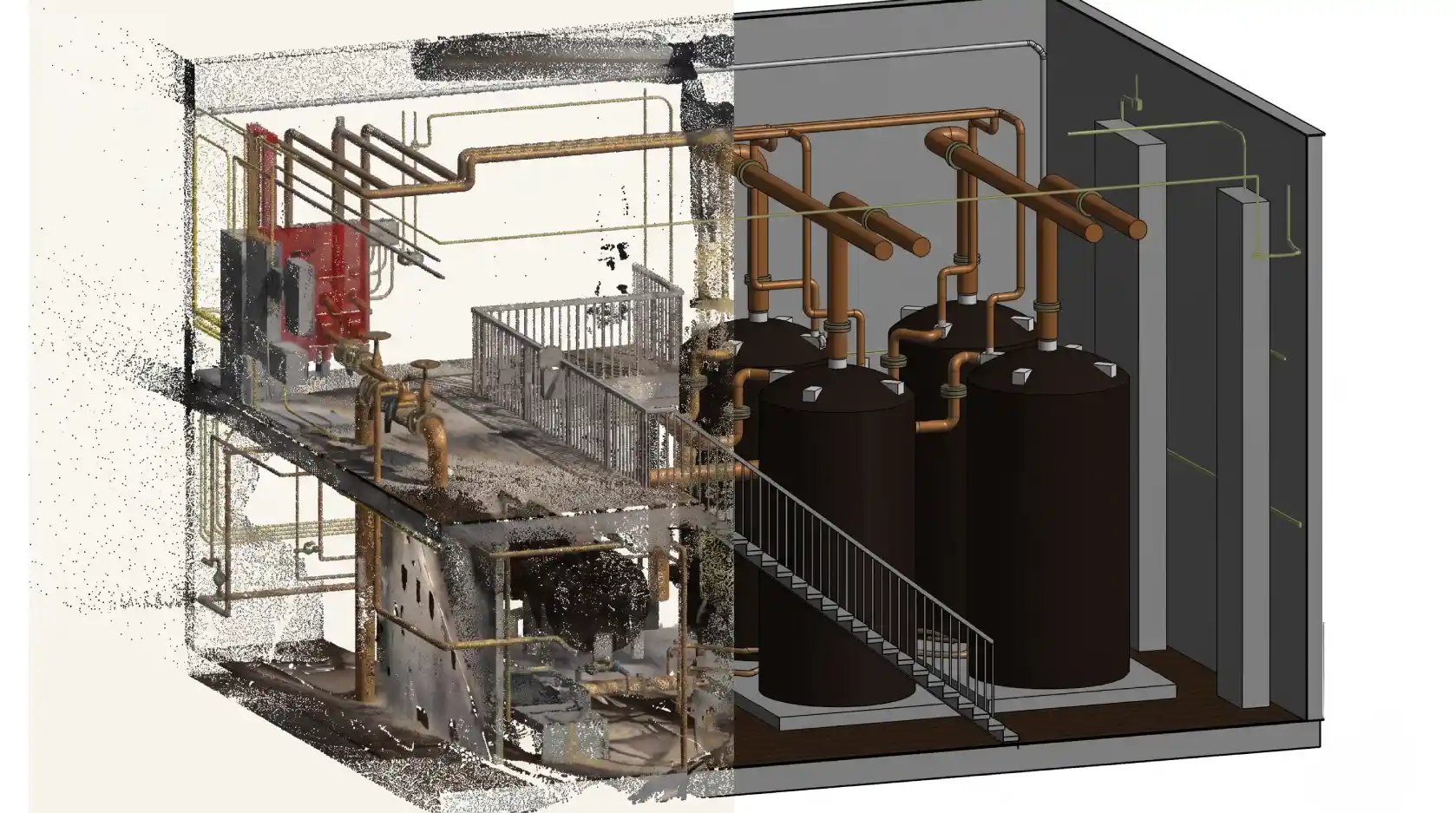
The services that heat, cool, power and supply a building run through spaces that are often the most constrained, congested and the hardest to survey by hand. Ceiling voids packed with overlapping duct runs, pipe routes that change direction without documentation. None of this is easy to measure with a tape measure and a clipboard.
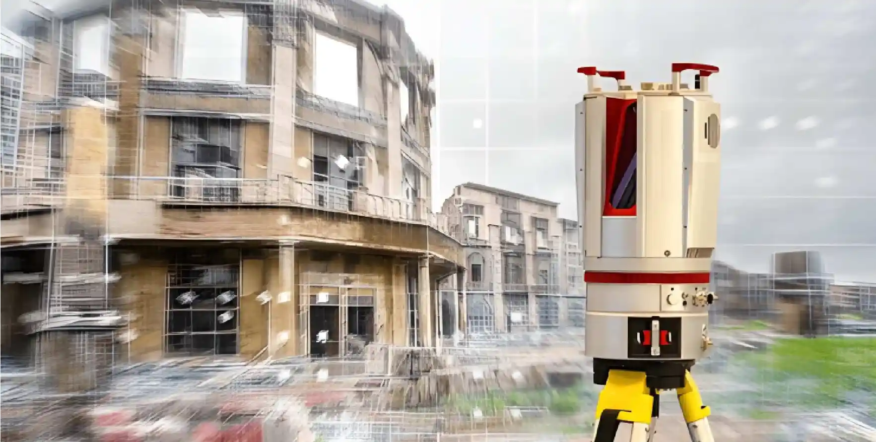
Laser scanning changes that entirely. It is uniquely suited to MEP surveys because it works in the same environments where manual survey falls short. The resulting point cloud becomes the basis for a model your engineers can actually rely on.
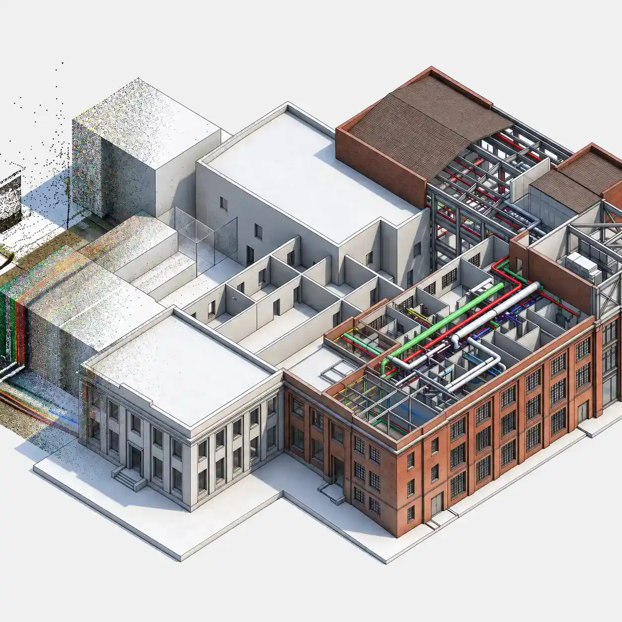
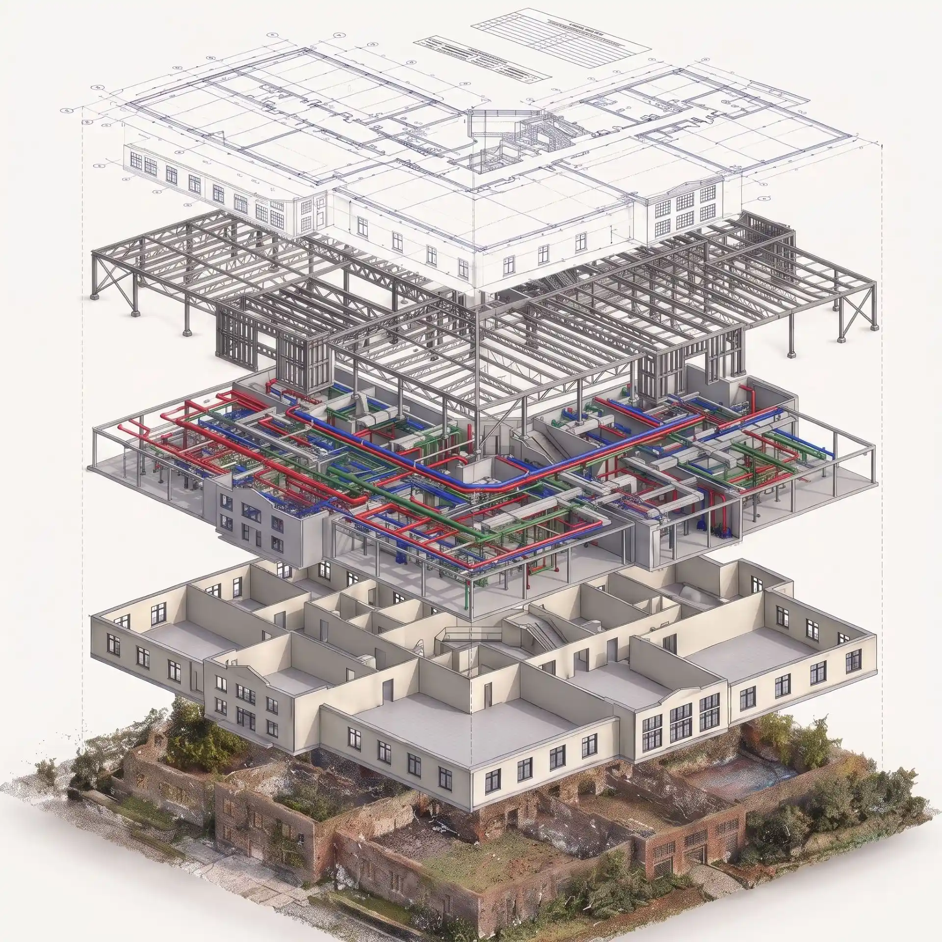
Scan to BIM produces MEP BIM models directly from your point cloud data, covering all three engineering disciplines (mechanical, electrical and plumbing) in a single co-ordinated workflow. Every element is modelled as a parametric Revit element with verified routing, sizing and spatial co-ordinates, ready for retrofit design, clash detection, or FM asset management.
Six Project Triggers
An MEP BIM model becomes essential at each of these project stages.

Retrofit & Decarbonisation
Energy engineers needing an accurate existing services model as the verified base for HVAC or electrical retrofit design.
Congested Void Surveys
Project teams needing spatial data from congested ceiling voids before routing new services through occupied or constrained buildings.
Healthcare & Clean Rooms
Facilities teams requiring precise existing service models for healthcare, laboratory or cleanroom environments.
FM & Asset Management
Facilities managers building an as-installed MEP model tagged with asset data for planned maintenance and CAFM integration.
MEP Co-ordination Backdrop
BIM co-ordinators needing verified existing services geometry as the backdrop for new MEP design co-ordination and clash detection.
Condition & Services Survey
Building owners or engineers documenting existing services condition and routing for dilapidations, lease or compliance purposes.
MEP Scan to BIM vs. Manual Building Services Survey
Here is what changes when your MEP model is built from scan data rather than a manual services survey.
Manual surveys require access to ceiling voids, risers and plant rooms, which is often disruptive in occupied buildings.
Every service visible in the point cloud is modelled across all scanned zones.
Pipe and duct sizes estimated visually. Accurate dimensioning requires direct measurement.
All element dimensions traced from verified millimetre-accurate scan geometry; no estimation required.
Routing paths approximated. Accurate co-ordinates for above-ceiling runs rarely achieved.
Exact routing paths, invert levels and spatial co-ordinates are modelled for every service in the scan.
Produces 2D schematic drawings that cannot be used for co-ordination or scheduling in a BIM environment.
Produces parametric BIM model. Schedules, clash checks and CAFM integration all built in.
Difficult to record service congestion accurately; visual diagrams don't convey spatial density.
Exact congestion geometry modelled. This is critical for routing new services through constrained voids.


What You Receive
Scope, disciplines and LOD are confirmed at start. Every element is QA-reviewed against the source scan before issue.
| Deliverable | Scope & Detail |
|---|---|
| Mechanical (HVAC) Model | Ductwork, AHUs, FCUs, VAV boxes, diffusers, grilles and mechanical plant modelled with verified sizes, routing and connection points. |
| Electrical Model | Cable trays, trunking, conduit, distribution boards, LV panels and busbar systems modelled with routing and spatial co-ordinates. |
| Plumbing & Drainage Model | Pipework across hot, cold, heating and chilled water systems (valves, tanks, pumps, sanitary ware and drainage), as installed. |
| Ceiling Void & Riser Model | Above-ceiling and riser zone services modelled to the exact congestion geometry shown in the scan. This is critical for routing new services without clashes. |
| Central & Distributed Plant | Boilers, chillers, cooling towers, pumps and roof plant modelled with connection positions and spatial footprints. |
| MEP Clash Detection Report | MEP model checked against architectural and structural models in Navisworks, clashes flagged with location and priority. |
| COBie Asset Data | Equipment tagged with manufacturer, model, install date and maintenance interval for CAFM integration at LOD 400 on request. |
| Issue Formats | Native Revit .rvt, IFC 2x3 or IFC 4, Navisworks .nwc, version-matched, with MEP content schedule and transmittal. |
Level of Detail | Up to LOD 500
We confirm the required LOD at the scope stage. Most retrofit and FM projects specify LOD 350 or 400.
LOD 300
300- Approximate service routing
- Plant positions and approximate sizes
- Discipline-level spatial co-ordinates
 For: scoping, early retrofit design
LOD 350
350- Accurate routing with invert levels
- Connection points and interfaces shown
- Clash-detection-ready with other disciplines
For: co-ordination, retrofit engineering
LOD 400
400- Full component geometry and sizing
- COBie parameters on all equipment
- FM-ready asset data throughout
For: FM, CAFM, healthcare, decarbonisation
How It Works
Every project follows a structured five-stage process from scope agreement through to reviewed issue.
Who Avails Our MEP Scan to BIM Services
Six client types who regularly commission MEP Scan to BIM.

MEP Engineers & Designers
Verified existing services models as the base for retrofit, extension and new MEP design in existing buildings.
Healthcare & Critical Facilities
Precise existing services models for hospitals, laboratories and clean rooms where accuracy underpins compliance.
Retrofit & Refurbishment Contractors
Accurate as-installed MEP models for construction management and co-ordination in occupied or constrained spaces.
Energy & Decarbonisation Consultants
Existing HVAC and electrical models as the verified base for decarbonisation assessments and Net Zero retrofit.
Facilities Managers
FM-ready MEP models tagged with COBie data for planned maintenance and CAFM integration.
Survey Companies
Extend your deliverable set with production-quality MEP Revit model output from your scan data.

Related Services
MEP Scan to BIM is part of our full Scan to BIM service list.
Need an accurate MEP model of your building's existing services?
Scan to BIM delivers scan-derived MEP BIM models for engineers, contractors and FM teams.
Contact Us
Frequently Asked Questions
Our service covers all three MEP disciplines: Mechanical (ductwork, AHUs, HVAC plant and distribution), Electrical (cable trays, trunking, conduit, distribution boards) and Plumbing (pipework, drainage, valves, tanks and sanitary ware). All three are modelled from the same point cloud in a single co-ordinated workflow.
Yes. The scan-derived MEP model is structured for Navisworks or Revit co-ordination environment alongside new design models. Clash detection between existing and proposed services is one of the most common uses of this deliverable.
Yes. All disciplines are modelled from the same point cloud and shared co-ordinates, so they can be federated at any time.
Yes, provided the scan covers them. We model every service that is visible in the point cloud, including dense, overlapping runs. If the void was not scanned, we flag the gap before modelling starts.
LOD is confirmed at the scope stage. LOD 300 suits early scoping and retrofit feasibility. LOD 350 is typical for co-ordination and retrofit engineering. LOD 400 is specified where full COBie asset data and FM-ready parameters are required throughout.
Start Your Scan to BIM Project
Send us your scan data details, point cloud format and project requirements. We will review your brief, confirm scope and have the right team allocated within 48 hours.
NDA Protected
All scan data, project files and client information handled under strict NDA.
100% Confidential
Your data stays yours. We guarantee full confidentiality throughout the project.
24-Hour Response
Send us your brief today. You’ll hear back from our team within one business day.