Structural Scan to BIM Services
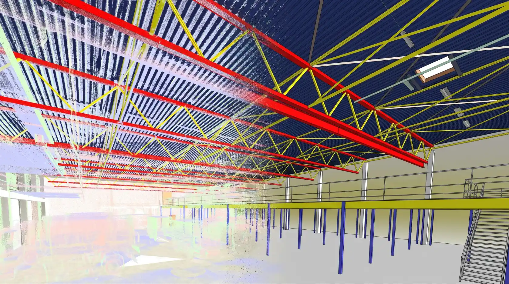
The structural frame of your building, modelled exactly as it was erected, with member sizes, connections and grid lines verified against the scan.

Years of Experience
Successful Projects
Countries Served
Happy Clients
Verified Steel Structure Models From Your Scan Data
Original fabrication drawings tell you what was specified. However, they don't tell you what was actually erected, what's happened to the frame since, or whether on-site fabrication decisions changed anything along the way. For older buildings, those drawings may not exist at all.
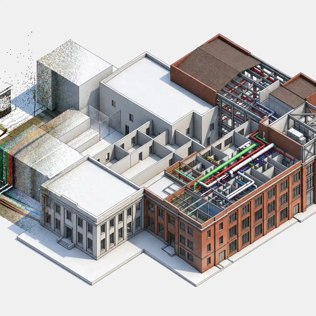
A structural model built from current scan data resolves all of these uncertainties. It shows the structure as it stands today, regardless of what records do or don't survive. This matters most when engineering decisions depend on it. Engineers reviewing the model see the condition as it actually is, which is the information a structural assessment needs.
Scan to BIM produces structural steel BIM models directly from your scan data. Our scope is steel structure specifically, including beams, columns, connections, bracing and the grid lines and levels that define the frame, modelled as parametric Revit elements at the Level of Detail your engineering team needs.
Six Project Triggers
A structural steel BIM model becomes essential at each of these project stages.

Steel-Framed Refurbishment
Engineers needing a verified existing steel model before scoping alterations, extensions or load reassessment.
Structural Capacity Checks
Structural engineers assessing whether existing steel can support new loads, additional storeys or a change of use.
MEP Co-ordination & Clash
Project teams needing an accurate steel model for MEP routing and clash detection in retrofit projects.
Industrial & Warehouse Surveys
Owners and engineers documenting existing steel-framed industrial buildings for capacity assessment or repurposing.
Fire & Compliance Assessment
Fire engineers and compliance teams requiring accurate member sizes and fire protection coverage for compliance reviews.
Steel FM & Asset Records
Facilities teams building a parametric structural record for maintenance, inspection and lifecycle management.
Scan-Verified Steel vs. Original Fabrication Drawings
This is what changes when your structural model is built from scan data rather than archived drawings.
Reflects design intent, assuming the steel was erected exactly to drawing.
Reflects what was actually erected, including any on-site fabrication changes.
No record of deflection, distortion or condition since original construction.
Shows the current as-built condition, including deflection and distortion where visible in the scan.
Often missing or unavailable for older buildings with no surviving records.
Generated fresh from your scan regardless of whether original drawings exist.
Connection details shown are design specifications, not verified as-built.
Connection positions and member relationships verified against scan geometry.
Risk of clash failures when used as base for retrofit MEP or extension design.
Verified spatial co-ordinates reduce clash risk in retrofit and co-ordination work.


What You Receive
Scope and LOD are confirmed at start. Every member is QA-reviewed against the source scan before issue.
| Deliverable | Scope & Detail |
|---|---|
| Steel Beam & Column Model | Primary and secondary steel members modelled with verified section sizes, positions and orientations from scan geometry. |
| Connection Detail References | Connection types and locations identified and modelled to representative geometry (bolted, welded and bearing connections). |
| Bracing & Lateral Stability | Wind bracing, cross-bracing and lateral stability systems modelled with verified member sizes and connection points. |
| Grid Lines & Levels | Structural grid established from scan geometry, with verified floor-to-floor heights and steel datum levels throughout. |
| Deflection & Condition Notes | Where visible deflection or distortion is present in the scan, this is flagged and noted against the affected members. |
| Clash Detection Report | Steel model checked against other discipline models in Navisworks. Clashes flagged with location and priority. |
| Structural Drawing Sheets | Plan, elevation and section sheets extracted from the model, with member schedules, grid references and levels at agreed scales. |
| Issue Formats | Native Revit .rvt, IFC 2x3 or IFC 4, Navisworks .nwc version-matched, with model content schedule and transmittal. |
Level of Detail | Up to LOD 500
We confirm the required LOD at the scope stage. Most structural retrofit projects specify LOD 350 or 400.
LOD 300
300→ For: design co-ordination, capacity checks
LOD 350
350→ For: MEP co-ordination, retrofit design
LOD 400
400→ For: condition surveys, FM, fire compliance
How It Works
From scope to handover, every structural BIM project follows the same structured workflow.
Who Avails Our Structural Scan to BIM Services
Six client types who regularly commission Structural Scan to BIM from us.

Structural Engineers
Verified existing steel models as the base for capacity assessment, alterations and extension design.
Fire Engineers & Compliance Teams
Verified member sizes and fire protection coverage for compliance and fire strategy reviews.
Main & Steel Contractors
Accurate as-built steel models for retrofit, refurbishment and construction co-ordination programmes.
Facilities Managers
Parametric structural records with member data for inspection, maintenance and lifecycle management.
MEP Engineers & Co-ordinators
Reliable steel backdrop for routing new services and clash detection in occupied or constrained buildings.
Survey Companies
To extend their deliverable set with production-quality structural Revit model output from scan data.
Related Services
Structural Scan to BIM is part of our full range of services.
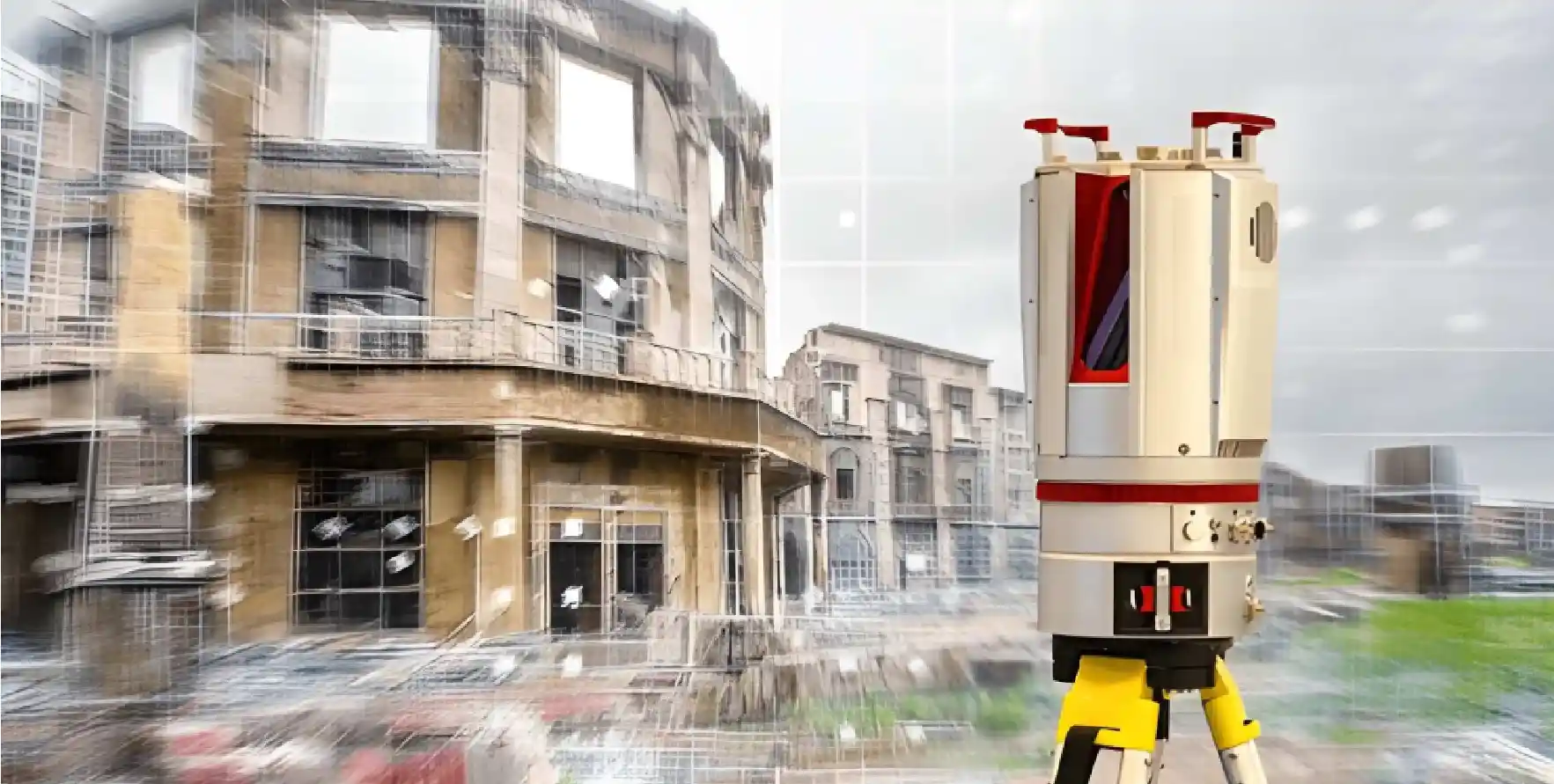
Need a verified steel structure model of your existing building?
Scan to BIM delivers scan-derived structural steel BIM models for engineers, contractors and FM teams.
Get in Touch
Frequently Asked Questions
Our service covers steel structure only (beams, columns, connections, bracing and steel framing elements, modelled as constructed). It does not include in-situ concrete, timber or masonry structure. It also does not include architectural fabric (covered by Architectural Scan to BIM) or MEP services (covered by MEP Scan to BIM).
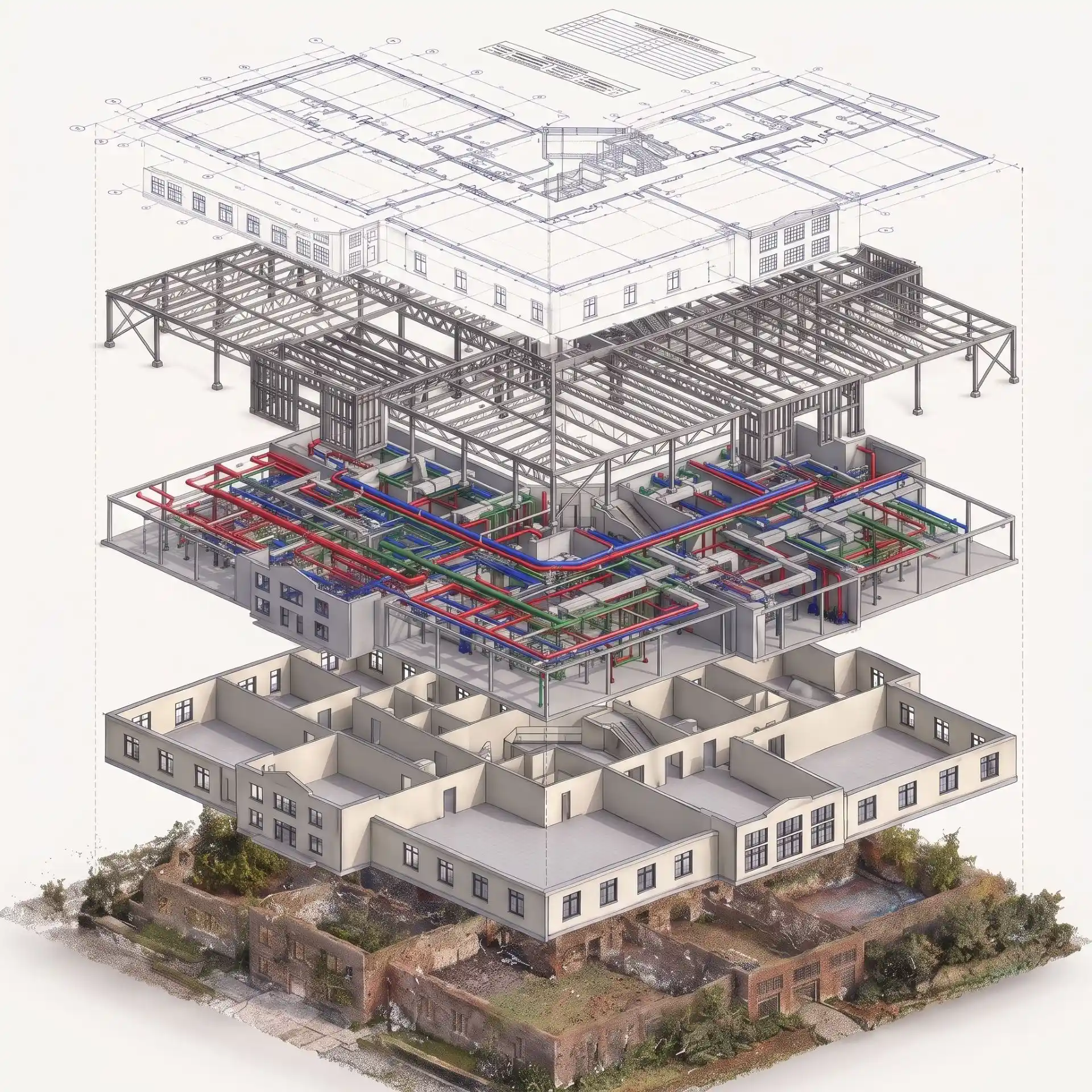
Yes. All disciplines are modelled from the same point cloud and shared co-ordinates, so they can be federated at any time.
We model connection types and positions to representative geometry appropriate to the agreed LOD. For full fabrication-level connection detailing (bolt patterns, weld specifications and plate thicknesses) we recommend co-ordination with a structural engineer or steel detailer using our model as the verified base.
LOD is confirmed at scope stage. LOD 300 suits design co-ordination and capacity checks. LOD 350 is typical where the model will co-ordinate with new MEP or retrofit design. LOD 400 is specified for condition surveys, FM records and fire compliance work.
Start Your Scan to BIM Project
Send us your scan data details, point cloud format and project requirements. We will review your brief, confirm scope and have the right team allocated within 48 hours.
NDA Protected
All scan data, project files and client information handled under strict NDA.
100% Confidential
Your data stays yours. We guarantee full confidentiality throughout the project.
24-Hour Response
Send us your brief today. You’ll hear back from our team within one business day.